
Model predictive control for single-phase three-level grid-connected F-type inverters


Abstract
This paper presents a model predictive control (MPC) method for single-phase three-level grid-connected F-type inverters. The main control objective in grid-connected inverters is to regulate the grid current with low total harmonic distortion. Since the F-type inverter has emerged recently, there is no specific control method developed for this inverter topology in the literature yet. In this paper, the mathematical model of the F-type inverter and the design of model predictive control is presented. Since the dc capacitor voltage balancing is essential for F-type inverters, both current control and dc capacitor voltage controllers are combined in a multi-objective cost function. Thus, the control of the dc and ac sides of the F-type inverter is achieved successfully. The theoretical considerations were verified through simulation studies. The effectiveness of the proposed MPC method was investigated in the steady state as well as dynamic transients under variations in grid current, input dc voltage, and grid voltage. The simulation results show that the grid current and dc capacitor voltages are successfully controlled in all operating conditions.
Keywords
1. INTRODUCTION
The high demand for electrical energy in commerce as well as industry has increased the importance of renewable energy sources in the last decades. The integration of renewable energy sources to the grid can be accomplished by using inverters. Therefore, the use of various inverters in such applications is increasing day by day. Initially, traditional two-level voltage source inverters were widely preferred in the grid-connected applications. However, multilevel inverters have gained importance due to the low harmonic distortions in output voltage and current[1-4]. In addition, operating under low switching frequencies and low voltage stress can be specified as the other advantages of multilevel inverters[5].
Mainly, three different multilevel topologies, namely cascaded H-bridge (CHB)[6], flying capacitor (FC)[4], and neutral point clamped (NPC)[7], inverters are presented in the literature. The features and applications of these three topologies are different[1,8]. Since CHB inverters require isolated and symmetrical input sources for each H-bridge, they are preferred in multi-source systems[9]. However, the generation of the multi-level voltages in CHB inverters using a single power source is a challenging issue. Therefore, CHB inverters are not suitable for such systems. Switching device configurations of conventional diode clamped NPC and FC topologies are the same[10,11]. On the other hand, the middle-level voltages in both FC and NPC inverters are provided by capacitor voltages. However, the number of capacitors increases depending on the level of the inverter and the phase number in the FC topology. Therefore, the requirement of many capacitors and high capacitance in FC topologies is specified as the main disadvantage[5]. The capacitor number in NPC inverters is not dependent on phase number. Therefore, the required capacitance and cost are lower than FC topologies. In addition, the control of capacitor voltages in FC topologies is more complicated than in NPC inverters[12].
The diode clamped topology is the base model of the neutral point clamped inverters. Since the required diode number is dependent on voltage levels, it becomes a challenging issue for diode-clamped NPC inverter applications. T-type inverters have the same features as the NPC topology[13]. The main advantage of the T-type inverter compared to NPC inverters can be specified as the elimination of the diode requirement. Similar to the NPC topology, series-connected capacitors are used in the dc side of T-type inverter. Contrary to NPC inverters, the neutral point is connected through bidirectional switches in the T-type inverter. Hence, the diode requirement is eliminated. Among the multilevel inverter topologies, the T-type inverter has fewer components[13]. The F-type inverter was recently derived from the T-type inverter topology[14]. In T-type inverters, 50% of switches should have a full dc-link reverse blocking voltage rating while it is 25% in F-type inverters[14]. Therefore, the cost and losses of F-type inverters are lower than those of T-type inverters. Similar to the diode-clamped NPC and T-type topologies, the voltage levels are obtained using dc side capacitor voltages in the F-type inverter. Therefore, the capacitor voltages should be well-balanced to achieve voltage levels properly.
In addition to topologies, the control methods are important for the proper operation of the inverter. However, the control of F-type inverters has not been reported in the literature yet. In general, the control objectives for a grid-connected inverter can be specified as low total harmonic distortion (THD) in the grid current, fast dynamic response, and robustness to disturbances in input and output variables[15]. In addition, dc capacitor voltage balancing is essential in controlling of NPC, T-type, and F-type topologies[16,17]. The nonlinear control methods offer fast dynamic response under variations in operating point. For this reason, the model predictive control (MPC) and sliding mode control (SMC) methods have gained great attention in the last decade[18-20]. The performance of the SMC method is independent of the system parameters[21]. Besides this advantage, the chattering and determining the controller gain are the key challenges[22]. Especially, the controller gains have an effect on the controller performance. However, the gain tuning method is not available in the literature yet. In addition, the design of the SMC method for controlling systems with many variables can be stated as another challenge[22]. It is worth noting that the switching signals are generated by using modulation schemes or hysteresis band in most of the sliding mode controllers[16,23]. The complexity of modulation schemes is dependent on the switch number of power converters. Therefore, the implementation of the control method becomes complex. Although the finite control set (FCS) concept causes variable switching frequency, FCS is widely preferred in controlling power converters due to the capability of eliminating the complex modulation schemes. Since the combination of FCS structure and MPC method exhibits an excellent performance, the FCS-MPC method is employed in controlling complex power converters[13]. The MPC is structured based on the mathematical model of the system. The key feature of the MPC method is the ability to solve multi-objective control problems using a total cost function[24]. As mentioned above, the control of both grid current and dc side capacitor voltages should be accomplished at the same time for proper operation of F-type inverters. Therefore, the control problem of the F-type inverter is a multi-objective function.
Since F-type inverters have emerged recently, control of these inverters has not been reported in the literature yet. In this paper, an MPC method is proposed for single-phase three-level grid-connected F-type inverters. As mentioned above, the proper operation of F-type inverter can be achieved by controlling both grid-current and capacitor voltages. Therefore, the choice of MPC is due to its multi-objective cost function feature. The effectiveness of the proposed method was investigated in simulation studies under both steady-state and dynamic conditions.
2. MODELING OF F-TYPE INVERTERS
A single-phase three-level grid-connected F-type inverter is depicted in Figure 1. Clearly, each leg of the F-type inverter consists of four switches. The switching configurations of the single-phase F-type inverter are given in Table 1. Figure 2 shows the equivalent circuits of the F-type inverter based on the switching states in Table 1. Similar to the three-level T-type topology, five different voltage levels can be achieved at the output of the inverter. There are nine different switching states, and three of them (States 1, 5, and 9) generate 0, two of them (States 2 and 3) generate Vdc/2, and two of them (States 6 and 7) generate -Vdc/2.
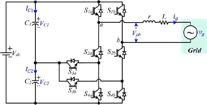
Figure 1. Single-phase F-type inverter.
Inverter output voltage under switching states
| State | Vab | ||||
|---|---|---|---|---|---|
| 1 | ON | ON | ON | ON | 0 |
| 2 | ON | ON | OFF | ON | VC1 = Vdc/2 |
| 3 | OFF | ON | OFF | OFF | VC2 = Vdc/2 |
| 4 | ON | ON | OFF | OFF | Vdc |
| 5 | OFF | ON | OFF | ON | 0 |
| 6 | OFF | ON | ON | ON | -VC1 = -Vdc/2 |
| 7 | OFF | OFF | OFF | ON | -VC2 = -Vdc/2 |
| 8 | OFF | OFF | ON | ON | -Vdc |
| 9 | OFF | OFF | OFF | OFF | 0 |
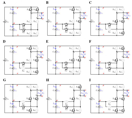
Figure 2. Equivalent circuits based on Table 1: (A) State 1; (B) State 2; (C) State 3; (D) State 4; (E) State 5; (F) State 6; (G) State 7; (H) State 8; and (I) State 9.
As shown in Table 1, ±Vdc/2 can be provided from C1 or C2 capacitors depending on switching states. Even though these switching states generate the same voltage levels, the charge or discharge statuses of C1 and C2 are different in the relevant states. On the other hand, VC1 and VC2 should be equal to half of Vdc to obtain the required voltage levels properly. In the other words, VC1 and VC2 should be balanced for the proper operation of the F-type inverter.
As clearly seen in the equivalent circuits, S1a is exposed to Vdc in the 7th, 8th, and 9th switching states [Figure 2G-I]. In addition, S1b is exposed to Vdc in the 3rd, 4th, and 9th switching states [Figure 2G-I]. Therefore, the blocking voltage of S1a and S1b should be equal to or higher than Vdc. On the other hand, the other switches are series connected. Therefore, their voltage level can be half of Vdc. This fact reduces the total cost, system size, and switching losses[14] of the F-type inverter.
The output voltage of the inverter can be written in terms of switching states as follows:
where VC1 and VC2 are the voltages of C1 and C2 capacitors, respectively. The output voltage can also be obtained as in Equation (2) by applying Kirchhoff’s voltage law to Figure 1.
where ig is the current injected to the grid, r is the resistance of inductor, L is the filter inductance, and vg is the grid voltage.
The derivative of the grid current can be written by using Equation (2) as follows:
Similar to Vab, the capacitor currents (IC1 and IC2) can be defined in terms of switching states by
Now, the derivative of the capacitor voltages can be written as follows:
3. DESIGN OF MODEL PREDICTIVE CONTROL FOR F-TYPE INVERTERS
In this section, the MPC of the three-level grid-connected F-type inverter is introduced. There are three control variables (ig, VC1, and VC2) to be controlled. Since the MPC method is able to control more than one variable by using a multi-objective cost function, it is preferred for controlling F-type inverters. The design of MPC method can be summarized in three steps: prediction, calculation of the total cost function, and minimization. Predictive equations of the control variables can be obtained by using forward Euler approximation as
where ig(k + 1) is the predicted value of the grid current at (k + 1)th sampling instant and Ts is the sampling time. Now, substituting Equation (3) into Equation (8) gives the predictive equation of the grid current as
where Vab(n) is the output voltage, which is obtained by using Equation (1).
Next, the predicted values of the capacitor voltages at (k + 1)th sampling instant can be obtained by substituting Equations (6) and (7) into Equation (8) as follows:
The predictive equations of all the control variables are obtained. Now, the cost functions can be written in terms of the errors between predicted and reference variables. The cost function for the grid current can be written as
where
As mentioned above, the dc side capacitor voltages should be balanced. Therefore, the references of VC1(k) and VC2(k) should be equal to Vdc/2. Hence, the error between VC1(k) and VC2(k) will be zero in the steady state. Therefore, the second cost function can be written as the error between VC1(k + 1) and VC2(k + 1) as follows:
Now, cost functions can be combined in a multi-objective total cost function as follows:
where λ is the weighting factor that is used to determine the weight of different cost terms in the multi-objective cost function.
The flowchart of the proposed MPC algorithm is depicted in Figure 3. The algorithm starts with the measurements of the system variables. Thereafter, the predicted values of the control variables at (k + 1) sampling instant are calculated for the nine possible switching states in Table 1. At the same time, the cost function in Equation (14) is also calculated for each possible switching state, and each cost function value is stored in the control software. After these calculations, the obtained cost results are evaluated using minimization, and the minimum cost value is found. Finally, the optimal switching vector is selected depending on the minimum cost results. In other words, the switching vector which gives the minimum cost result is selected as optimal.
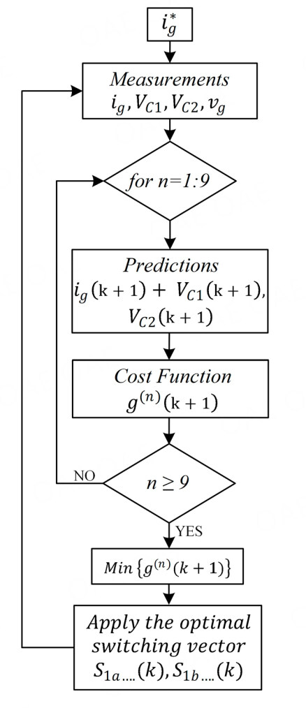
Figure 3. Flowchart of the proposed MPC.
4. SIMULATION RESULTS
Steady-state and dynamic responses of the proposed control method were investigated by simulation studies using MATLAB/Simulink environment. The block diagram of the proposed control strategy is depicted in Figure 4, while the system parameters are given in Table 2.
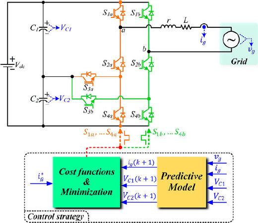
Figure 4. Block diagram of the proposed MPC.
System parameters
| Description and symbol | Value |
|---|---|
| Grid voltage amplitude: vg | 150 V |
| Input Voltage: Vdc | 200 V |
| Inductance: L | 5 mH |
| Inductor resistance: r | 0.1 Ω |
| DC capacitors: C1 and C2 | 470 µF |
| Weighting factor: λ | 0.001 |
| Sampling time: Ts | 30 µs |
4.1 Steady-state results
Figure 5 shows the steady-state responses of system variables. As shown in Figure 5A, the amplitude of the grid voltage is 150 V with 50 Hz fundamental frequency. Figure 5B shows the inverter output voltage. Since the input voltage (Vdc) of the inverter is 200 V, the maximum value of the output voltage is equal to Vdc. On the other hand, the middle-level voltages are equal to half of ±Vdc/2. Since the middle-level voltages are provided by VC1 and VC2, the capacitor voltages should be well-balanced. As shown in Figure 5C, VC1 and VC2 have different levels at the beginning of the simulation. Thereafter, VC1 and VC2 are successfully balanced by the proposed algorithm. As shown in Figure 5D, the dc side voltage error between VC1 and VC2 are balanced within ±1% error band. Figure 5E shows the grid current and amplitude of reference current. Clearly, the amplitude of the grid current is successfully regulated to reference. Similar to the dc side voltage error, the current tracking is achieved with ±0.5 A error. The errors on both dc and ac sides can be reduced by decreasing Ts. However, low Ts can only be used with a sophisticated microcontroller, which is an expensive solution in practice. Therefore, the effect of errors in THD, which is one of the important performance indicators, should be checked. Figure 6 shows the spectrum and THD results of the grid current. The THD is measured to be 1.1%, which meets the recognized standard.
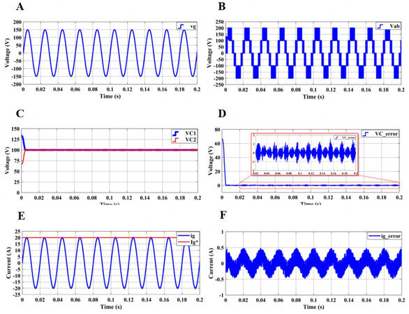
Figure 5. Steady-state responses of system variables: (A) grid voltage; (B) inverter output voltage; (C) capacitor voltages; (D) dc voltage error; (E) grid current and amplitude of reference current; and (F) grid current error.
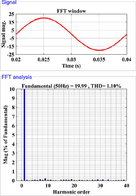
Figure 6. Spectrum of the grid current.
4.2 Dynamic response results
In addition to the steady-state performance, the dynamic responses are also important performance indicators in controlling grid-connected inverters. The dynamic response of the controller was tested under step change in reference current, and the results are presented in Figure 7. As shown in Figure 7A, the amplitude of the reference current
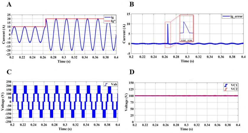
Figure 7. Dynamic responses under step change in reference current: (A) grid current and amplitude of reference current; (B) grid current error; (C) inverter output voltage; and (D) capacitor voltages.
The second dynamic response test is examined under variations in the input dc voltage. As shown in Figure 8A, Vdc is abruptly increased from 200 to 250 V. The results in Figure 8B show that the maximum value of Vab changes depending on Vdc. Furthermore, the voltage levels are generated properly after the step change. As mentioned above, the voltage levels are dependent on VC1 and VC2; therefore, the capacitor voltages should be regulated to half of Vdc. As shown in Figure 8C, both capacitor voltages are increased from 100 to 125 V. Clearly, the voltage balancing part of the proposed MPC successfully regulates the capacitor voltages under variations in Vdc. Moreover, the injected current to the grid is successfully regulated its reference in both Vdc values, as shown in Figure 8D.
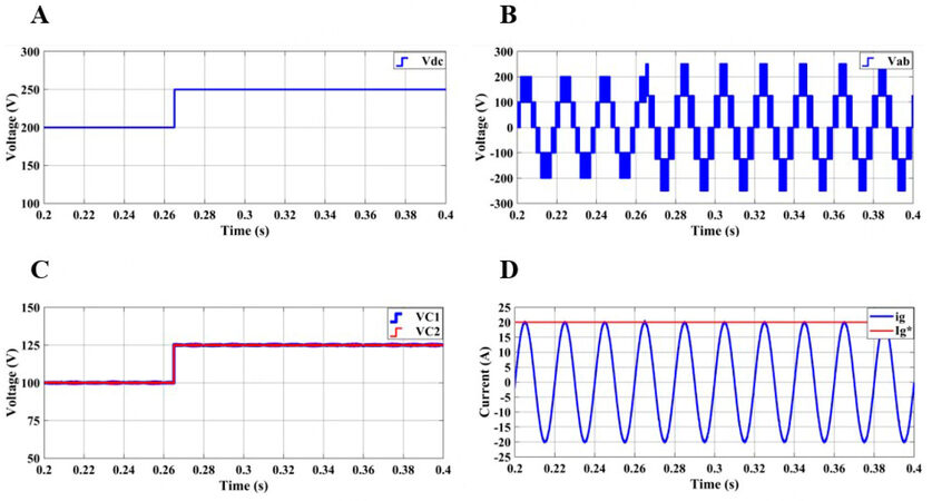
Figure 8. Dynamic responses under variations in input dc voltage: (A) input dc voltage; (B) capacitor voltages; (C) inverter output voltage; and (D) grid current and amplitude of reference current.
In the last dynamic response test, the effectiveness of the proposed controller is investigated under 20% decrement in the grid voltage. As shown in Figure 9A, the amplitude of the grid voltage is abruptly decreased from 150 to 120 V. VC1 and VC2 are balanced and ig is regulated to its reference in both grid voltage conditions, as shown in Figure 9B and C. Since the capacitor voltages are not changed during the simulation, voltage levels in Vab are not affected by the decrement in grid voltage. The decrement in the grid voltage affects the modulation level of the output voltage (Vab) in the grid connected inverter. As shown in Figure 9D, the third voltage level (between 100 and 200 V in Vab) in Vab is narrowed after the decrement. These results reveal that the proposed MPC method is able to control the F-type inverter under different grid conditions.
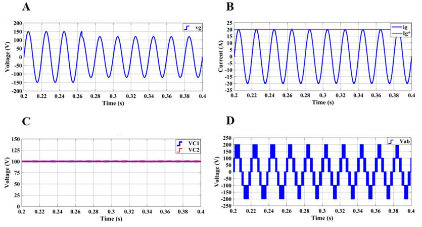
Figure 9. Dynamic responses under variations in grid voltage: (A) grid voltage; (B) grid current and amplitude of reference current; (C) capacitor voltages; and (D) inverter output voltage.
5. CONCLUSIONS
A model predictive control method is proposed for the single-phase three-level grid-connected F-type inverters which have emerged recently. The main objective of this study was to investigate the applicability of MPC in controlling F-type inverters. Since the capacitor voltages and grid current should be controlled at the same time to achieve the proper operation of F-type inverters, the multi-objective cost function feature of MPC method is used. The effectiveness of the proposed controller was investigated under steady-state operation. Furthermore, the dynamic response capability of MPC was tested under variations in reference current, input dc voltage, and grid voltage. The results show that the proposed method is capable of controlling the F-type inverter under both steady-state and dynamic operating conditions. Moreover, dc side capacitor voltages were regulated in all operating conditions by the proposed MPC method. Furthermore, THD results show that the distortions in the injected current to the grid met the recognized standard. Thus, the proposed MPC method together with F-type inverter can be considered as an alternative solution to existing control methods with T-type inverter.
DECLARATIONS
Author’s contributions
Writing - original draft, conducting simulations, writing - review & editing: Guler N, Komurcugil H, Biricik S, Karimi HR
Methodology: Guler N
Formal analysis, investigation, supervision: Komurcugil H
Literature survey, visualization: Biricik S
Conceptualization: Karimi HR
Availability of data and materials
Not applicable.
Financial support
None.
Conflicts of interest
All authors declared that there are no conflicts of interest.
Ethical approval and consent to participate
Not applicable.
Consent for publication
Not applicable.
Copyright
© The Author(s) 2021.
REFERENCES
1. Rodriguez J, Jih-sheng Lai, Fang Zheng Peng. Multilevel inverters: a survey of topologies, controls, and applications. IEEE Trans Ind Electron 2002;49:724-38.
2. Yang Y, Wen H, Fan M, Xie M, Chen R. Fast finite-switching-state model predictive control method without weighting factors for T-Type three-level three-phase inverters. IEEE Trans Ind Inf 2019;15:1298-310.
3. Altin N, Ozdemir S. Three-phase three-level grid interactive inverter with fuzzy logic based maximum power point tracking controller. Energy Conversion and Management 2013;69:17-26.
4. Laamiri S, Ghanes M, Santomenna G. Observer based direct control strategy for a multi-level three phase flying-capacitor inverter. Control Engineering Practice 2019;86:155-65.
5. Bhatnagar J, Dave V. A comparative study of different topologies of multilevel inverters. International Journal of Electrical and Electronics Engineers 2017;9:2050-6.
7. Guler N, Irmak E. Design and control of multi - input multi - output DC-DC converter for neutral point clamped inverters. Gazi University Journal of Science Part C 2019;7:49-62.
8. Malinowski M, Gopakumar K, Rodriguez J, Pérez MA. A survey on cascaded multilevel inverters. IEEE Trans Ind Electron 2010;57:2197-206.
9. Kumar R, Thangavelusamy D. A modified nearest level modulation scheme for a symmetric cascaded H-bridge inverter. Gazi Univ J Sci 2019;32:471-481.
12. Dargahi V, Khoshkbar Sadigh A, Abarzadeh M, Pahlavani MRA, Shoulaie A. Flying capacitors reduction in an improved double flying capacitor multicell converter controlled by a modified modulation method. IEEE Trans Power Electron 2012;27:3875-87.
13. Komurcugil H, Bayhan S, Guler N, Blaabjerg F. An effective model predictive control method with self-balanced capacitor voltages for single-phase three-level shunt active filters. IEEE Access 2021;9:103811-21.
14. Odeh C, Lewicki A, Morawiec M, Kondratenko D. Three-level F-Type inverter. IEEE Trans Power Electron 2021;36:11265-75.
15. Sefa I, Ozdemir S, Komurcugil H, Altin N. Comparative study on Lyapunov-function-based control schemes for single-phase grid-connected voltage-source inverter with LCL filter. IET Renewable Power Generation 2017;11:1473-82.
16. Bayhan S, Komurcugil H. Sliding-mode control strategy for three-phase three-level T-type rectifiers with DC capacitor voltage balancing. IEEE Access 2020;8:64555-64.
20. Bayhan S, Trabelsi M, Abu-rub H, Malinowski M. Finite-control-set model-predictive control for a quasi-Z-source four-leg inverter under unbalanced load condition. IEEE Trans Ind Electron 2017;64:2560-9.
21. Komurcugil H, Biricik S, Bayhan S, Zhang Z. Sliding mode control: overview of its applications in power converters. IEEE Ind Electron Mag 2021;15:40-9.
22. Bagheri F, Komurcugil H, Kukrer O, Guler N, Bayhan S. Multi-input multi-output-based sliding-mode controller for single-phase quasi-Z-source inverters. IEEE Trans Ind Electron 2020;67:6439-49.
23. Topal M, Iskender I, Genc N. Sensorless speed control of a BLDC motor using improved sliding mode observer technique. Int J Tech Phys Probl Eng 2019;11:1-9.
Cite This Article
Export citation file: BibTeX | RIS
OAE Style
Guler N, Komurcugil H, Biricik S, Karimi HR. Model predictive control for single-phase three-level grid-connected F-type inverters. Complex Eng Syst 2021;1:2. http://dx.doi.org/10.20517/ces.2021.07
AMA Style
Guler N, Komurcugil H, Biricik S, Karimi HR. Model predictive control for single-phase three-level grid-connected F-type inverters. Complex Engineering Systems. 2021; 1(1): 2. http://dx.doi.org/10.20517/ces.2021.07
Chicago/Turabian Style
Guler, Naki, Hasan Komurcugil, Samet Biricik, Hamid Reza Karimi. 2021. "Model predictive control for single-phase three-level grid-connected F-type inverters" Complex Engineering Systems. 1, no.1: 2. http://dx.doi.org/10.20517/ces.2021.07
ACS Style
Guler, N.; Komurcugil H.; Biricik S.; Karimi HR. Model predictive control for single-phase three-level grid-connected F-type inverters. Complex. Eng. Syst. 2021, 1, 2. http://dx.doi.org/10.20517/ces.2021.07
About This Article
Copyright

Data & Comments
Data


 Cite This Article 36 clicks

 Like This Article 2
likes
Like This Article 2
likes


Comments
Comments must be written in English. Spam, offensive content, impersonation, and private information will not be permitted. If any comment is reported and identified as inappropriate content by OAE staff, the comment will be removed without notice. If you have any queries or need any help, please contact us at support@oaepublish.com.